Welcome to the creations of Daniel Busby. Click on any image to see more.
Check out my Blog for a lot more content!
Portfolio
-

A Moveable Feast
-

Robot Bartender
-
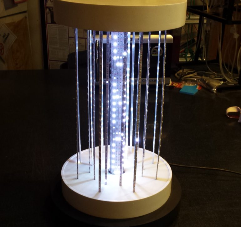
Pulse
-
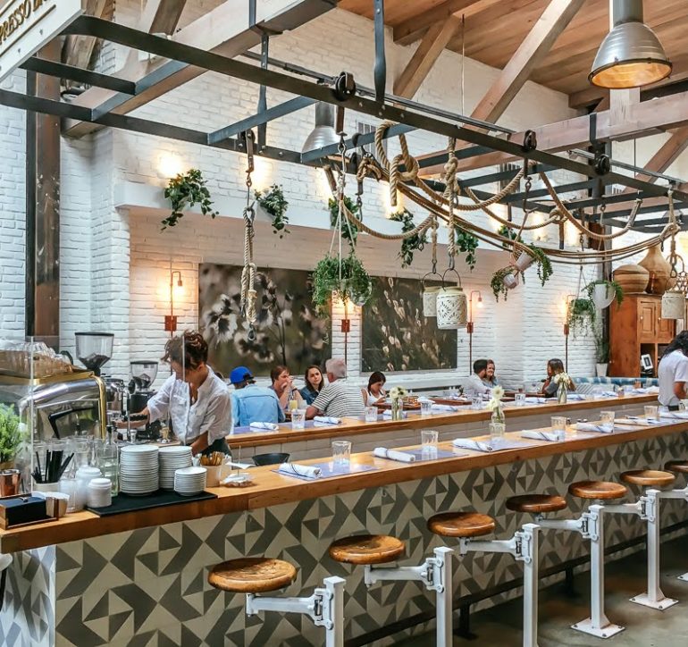
Butcher’s Rail
-
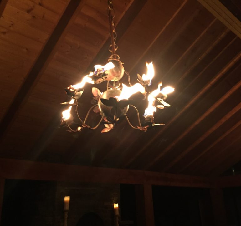
Fire Chandelier
-

MazelBot 2000
-

This Too Shall Pass
-

Custom Gate
-
Sparkfire
-
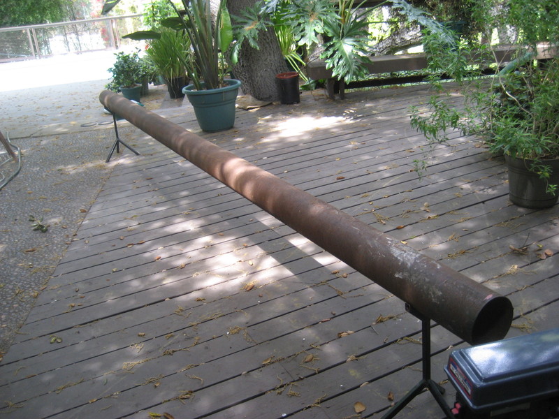
Rubens Tube